English
- English
- Español
- Português
- русский
- Français
- 日本語
- Deutsch
- tiếng Việt
- Italiano
- Nederlands
- ภาษาไทย
- Polski
- 한국어
- Svenska
- magyar
- Malay
- বাংলা ভাষার
- Dansk
- Suomi
- हिन्दी
- Pilipino
- Türkçe
- Gaeilge
- العربية
- Indonesia
- Norsk
- تمل
- český
- ελληνικά
- український
- Javanese
- فارسی
- தமிழ்
- తెలుగు
- नेपाली
- Burmese
- български
- ລາວ
- Latine
- Қазақша
- Euskal
- Azərbaycan
- Slovenský jazyk
- Македонски
- Lietuvos
- Eesti Keel
- Română
- Slovenski
- मराठी
- Srpski језик

"Energy Converters" in Power Grid Systems and Technological Evolution
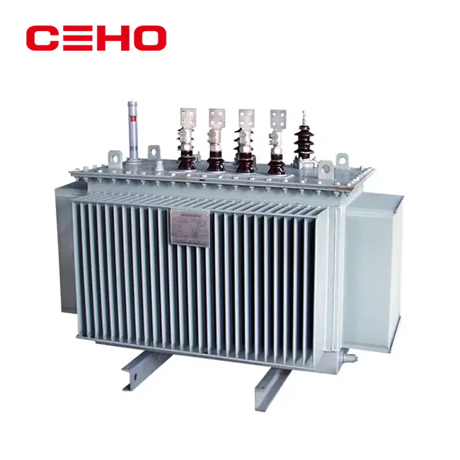
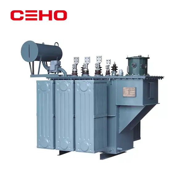
In modern power systems, there is a type of equipment that is indispensable like an "energy hub" - it connects the power generation end and the power consumption end, and through precise electromagnetic induction, it realizes the conversion of voltage levels, ensuring that power loss is reduced during long-distance transmission, while meeting the diverse power demands of industrial production and residents' lives. This type of equipment is called a power transformer. From the step-up transformers in large power stations, to the distribution transformers in urban substations, and then to the dedicated transformers in factory workshops, it runs through the entire chain of power transmission and distribution, and is the core equipment supporting social energy supply.
I. Core Principle of Power Transformers: The "Energy Magic" of Electromagnetic Induction
The working basis of power transformers originated from the law of electromagnetic induction discovered by Faraday in the 19th century. The core logic can be summarized as an energy conversion process of "electricity generating magnetism and magnetism generating electricity" : when the primary winding (input end) of the transformer is connected to an alternating current power supply, the current will generate an alternating magnetic field in the iron core. When this magnetic field passes through the secondary winding (output terminal), a corresponding electromotive force will be induced on the secondary side, and ultimately an alternating current proportional to the voltage on the primary side will be output.
In this process, the key to voltage conversion lies in the turns ratio of the primary and secondary windings. According to the principle of electromagnetic induction, the ratio of the primary voltage (U₁) to the secondary voltage (U₂) is equal to the ratio of the number of turns on the primary side (N₁) to the number of turns on the secondary side (N₂), that is, U₁/U₂ = N₁/N₂. For instance, the output voltage of a power station is typically 10 to 25kV. To achieve long-distance power transmission (reducing line losses requires increasing the voltage), a step-up transformer will boost the voltage to 110kV, 220kV, or even 1000kV through a "multi-turn secondary winding". When electricity is transmitted to the city or the user end, the distribution transformer reduces the high voltage to 10kV (for industrial use) or 220V/380V (for residential and commercial use) through the "fewer turns secondary winding", completing the voltage matching of "power generation - transmission - distribution".
It is worth noting that in an ideal state, the input power and output power of a transformer are equal (ignoring core losses and winding resistance losses), so the voltage and current have an inverse proportional relationship - when the voltage is increased, the current decreases (reducing the heat loss of the line), and when the voltage is decreased, the current increases (meeting the current demand of terminal equipment). This characteristic is precisely the key to efficient power transmission.
Ii. Core Structure: The Synergistic Effect of the four major components
The performance of a power transformer depends on the design and manufacturing level of its four core components, which jointly determine the efficiency, stability and service life of the equipment.
1. Core: The "path carrier" of magnetic field
The core is the core of the transformer's magnetic circuit. Its function is to guide the alternating magnetic field to pass through in a concentrated manner and reduce magnetic field leakage (i.e., "magnetic loss"). To reduce the eddy current loss generated by the core in an alternating magnetic field (the heat loss caused by the circulation of current within the core), modern transformer cores are typically made by laminating high-silicon steel sheets - the thickness of the silicon steel sheets is only 0.3-0.5mm, and their surfaces are coated with insulating coatings, which can effectively block the flow path of eddy currents. The structural design of the core (such as the lamination method and the jointing process) directly affects the magnitude of magnetic loss. Currently, the mainstream "stepped jointing" or "inclined jointing" technologies have been able to keep the core loss at an extremely low level.
2. Winding: The "core coil" for electrical energy conversion
The winding (commonly known as "coil") is the circuit part of a transformer, which is divided into the primary winding (connected to the power supply) and the secondary winding (connected to the load). It is usually wound with copper or aluminum wires (copper wires have better electrical conductivity and lower losses, and are often used in high-capacity transformers). The winding process of the windings must strictly control the arrangement density of the wires, the insulation thickness and the heat dissipation channels. The insulating paper or insulating varnish wrapped around the outer layer of the wires needs to withstand the breakdown test under high voltage (usually the insulation grade is required to reach Class A, Class B or Class H, corresponding to different upper temperature resistance limits). Meanwhile, the structure of the winding should reserve oil channels or air channels to ensure that the heat generated during operation can be dissipated in a timely manner.
3. Fuel Tank and Cooling System: The "Heat Dissipation Guarantee" of the equipment
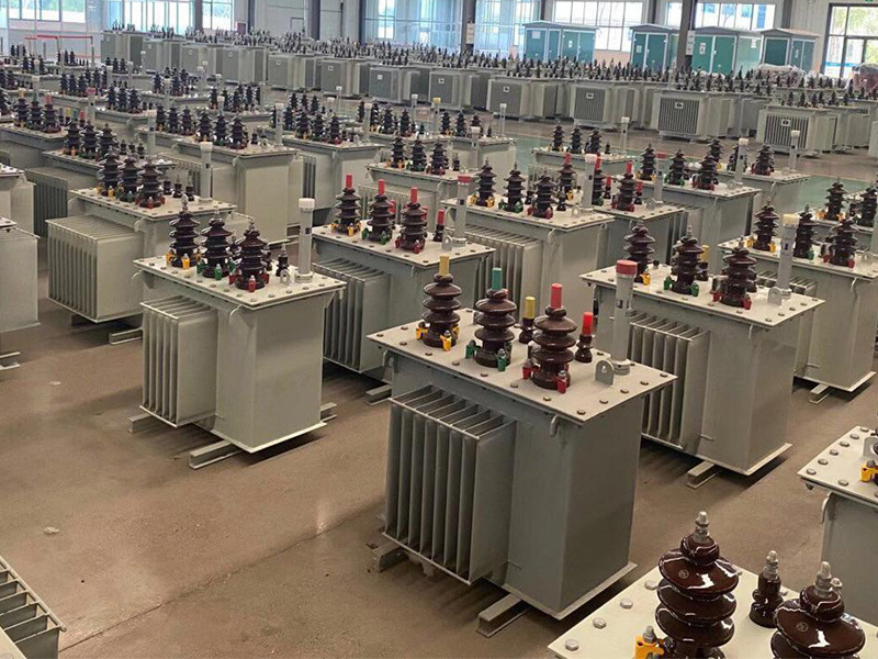
When a transformer is in operation, the core and windings will generate losses and convert them into heat. If the temperature is too high, it will accelerate the aging of insulation and even cause faults. Therefore, the oil tank and the cooling system are the key to ensuring the safety of the equipment: the inside of the oil tank is filled with transformer oil (which has both insulation and heat dissipation functions), and the heat is transferred to the tank wall through the natural convection or forced circulation of the oil. The exterior of the fuel tank is usually equipped with heat sinks (or heat dissipation tubes), which increase the contact area with the air and accelerate heat dissipation. For large-capacity transformers (such as those above 50MVA), forced oil circulation cooling systems (OFAF) or forced oil circulation directed cooling systems (ODAF) are also equipped. Through the coordinated effect of the oil pump and the fan, the heat dissipation efficiency is further enhanced.
4. Insulation and protection devices: The "safety barrier" of the equipment
In addition to the inter-turn insulation of the windings, the transformer also needs to be equipped with multiple insulation and protection components:
Insulating bushing: It is used to lead the lead-out wires of the winding from the interior of the oil tank and needs to withstand high voltage and atmospheric conditions. It is usually made of porcelain or composite insulating materials (such as epoxy resin).
Pressure relief valve: When a large amount of gas is produced in the fuel tank due to a fault (such as a short circuit) and the pressure rises sharply, the valve will automatically open to relieve the pressure and prevent the fuel tank from exploding.
Gas relay: Installed on the pipeline between the oil tank and the oil storage cabinet, it will trigger an alarm signal or directly cut off the power supply when a minor fault (generating a small amount of gas) or a serious fault (oil flow impact) occurs inside the transformer to prevent the fault from expanding.
Thermometer: It monitors the oil temperature in the fuel tank in real time. When the temperature exceeds the set threshold, it issues an alarm to ensure that the equipment will not be damaged due to overheating.
Iii. Types and Applications: "Energy Customization Solutions" Tailored to Different Scenarios
According to differences in voltage level, capacity, cooling method or application, power transformers can be classified into various types to adapt to different links of the power system.
By voltage level: Covering the entire chain of "power generation - transmission - distribution"
Step-up transformer: Located in a power station, it boosts the low voltage (10-25kV) output by the generator to high voltage (110kV-1000kV) for long-distance power transmission, with a typical capacity of 100-1000MVA.
Step-down transformers: They are classified into "main grid step-down" (such as 220kV to 110kV) and "distribution network step-down" (such as 110kV to 10kV, 10kV to 0.4kV). The former is used for power supply in regional power grids, while the latter directly serves industrial users or residential areas.
Ultra-high voltage transformers: With voltage levels of 750kV and above (such as 1000kV ultra-high voltage transformers in China), they are core equipment in ultra-high voltage transmission projects (such as "West-to-East Power Transmission"), and need to withstand extremely high voltages and currents, with extremely difficult manufacturing processes.
2. Classified by cooling method: Adapted to different capacity and environmental requirements
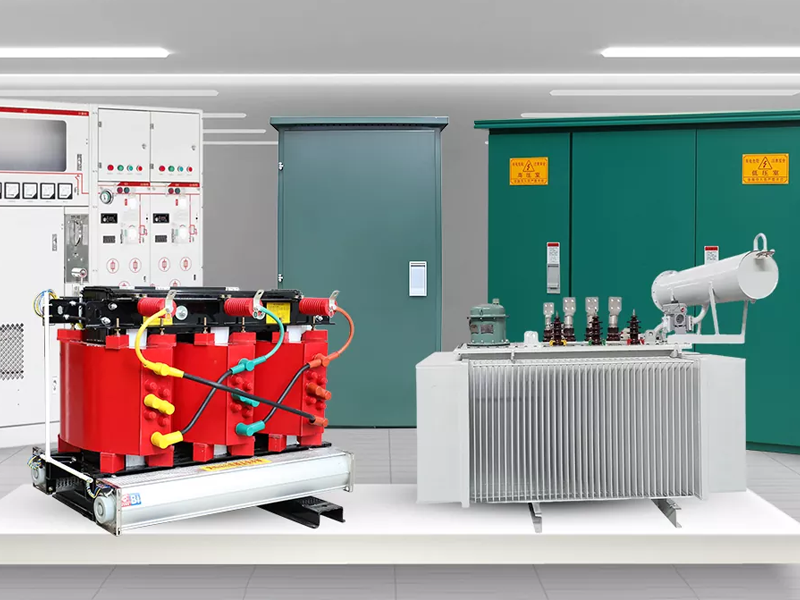
Oil-immersed transformer: Using transformer oil as the cooling medium, it has a mature structure and relatively low cost, and is suitable for outdoor substations or large-capacity scenarios (accounting for more than 80% of the total market).
Dry-type transformers: They use air or nitrogen as the cooling medium, have a high insulation grade (usually H-class), and good fire resistance. They are suitable for high-rise buildings, subways, hospitals and other places with high fire safety requirements, and their capacity is mostly below 20MVA.
3. Classified by usage: Meet specialized electricity demands
Distribution transformer: The most common type, used to reduce 10kV high voltage to 0.4kV low voltage, supplying residential buildings, shops, etc., with a capacity mostly ranging from 50 to 1600kVA.
Rectifier transformer: Used in industrial rectifier equipment (such as electrolytic aluminum, electroplating), it converts alternating current to direct current and needs to adapt to the harmonic impact of nonlinear loads.
Electric furnace transformer: Specifically designed for industrial electric furnaces (such as electric arc furnaces and induction furnaces), it outputs low voltage and high current, and needs to have strong overload capacity.
Autotransformer: The primary and secondary windings share a portion of the coil, which is small in size and low in loss. It is often used for voltage regulation in high-voltage transmission systems (such as tie transformers in 500kV systems).
Iv. Operation and Maintenance and Technological Trends: From "Stable Operation" to "Intelligent Upgrade"
The design life of power transformers is usually 20 to 30 years, but their actual service life depends on the level of operation and maintenance. The core of daily maintenance lies in "preventing faults", mainly including:
Oil quality monitoring: Regularly test the dielectric loss, breakdown voltage and moisture content of transformer oil to prevent deterioration of oil quality and decline in insulation performance.
Insulation testing: Through insulation resistance tests, dielectric loss tests, etc., the insulation condition between the windings and the core is evaluated.
Temperature monitoring: Real-time tracking of oil temperature and winding temperature to prevent overload operation;
Condition-based maintenance: By means of online monitoring technologies (such as online monitoring of dissolved gases in oil and online monitoring of partial discharge), the status of equipment can be grasped in real time, replacing the traditional "regular maintenance" and reducing downtime.
With the large-scale grid connection of new energy sources (wind power, photovoltaic power) and the construction of smart grids, power transformer technology is evolving in three major directions:
High efficiency and energy conservation: By adopting high-magnetic induction silicon steel sheets, low-loss conductors, and optimizing the core structure, the no-load loss and load loss are further reduced, meeting the energy efficiency requirements under the "dual carbon" goals (for instance, China's new national standard GB 20052-2022 has put forward higher requirements for the energy efficiency grades of transformers).
Intelligent upgrade: Integrating sensors, iot modules and edge computing capabilities, it enables real-time perception of equipment status, fault early warning and remote control. For instance, it predicts the trend of insulation aging through AI algorithms and schedules maintenance in advance.
Adapt to new energy: In response to the volatility and intermittency of new energy power generation, develop "new energy-specific transformers" with a wide voltage regulation range and strong harmonic resistance. At the same time, explore modular design to meet the flexible access requirements of distributed photovoltaic and energy storage power stations.
Related News
- Start by Choosing the Right JXF
- SG(B)10-10KV environmentally friendly dry-type transformer: How to deliver safe and green answers under non-encapsulated structure?
- What are the hazards of transformer overload operation? How to carry out real-time load monitoring?
- How can oil immersed transformers achieve future green development in the context of "dual carbon"?
- What does the internal structure of a dry-type transformer look like when disassembled?
- How to choose between power cabinet and lighting distribution box?
Leave me a message
New Products