English
- English
- Español
- Português
- русский
- Français
- 日本語
- Deutsch
- tiếng Việt
- Italiano
- Nederlands
- ภาษาไทย
- Polski
- 한국어
- Svenska
- magyar
- Malay
- বাংলা ভাষার
- Dansk
- Suomi
- हिन्दी
- Pilipino
- Türkçe
- Gaeilge
- العربية
- Indonesia
- Norsk
- تمل
- český
- ελληνικά
- український
- Javanese
- فارسی
- தமிழ்
- తెలుగు
- नेपाली
- Burmese
- български
- ລາວ
- Latine
- Қазақша
- Euskal
- Azərbaycan
- Slovenský jazyk
- Македонски
- Lietuvos
- Eesti Keel
- Română
- Slovenski
- मराठी
- Srpski језик

Do you know how a transformer works? From electromagnetic induction to high-efficiency conversion
Transformers, as the core equipment of modern power systems, have efficient and reliable power conversion capabilities that support almost all power applications from grid transmission to mobile phone charging. To understand how transformers achieve voltage conversion and energy transfer, we need to start from the basic principles of electromagnetic induction and gradually delve into their internal working mechanisms.
I. Electromagnetic induction: the basic working principle of transformer
1.1 The law of electromagnetic induction is the core theory of transformer operation, including Faraday's law of electromagnetic induction and Lenz's law. Faraday's law of electromagnetic induction states that when the magnetic flux passing through a closed loop changes, an induced electromotive force will be generated in the loop, and its magnitude is proportional to the rate of change of the magnetic flux. This discovery laid the foundation for quantitative research on electromagnetic induction phenomena and has been widely used in transformer design. Lenz's law further clarifies the direction of the induced current, that is, the magnetic field generated by the induced current always hinders the change in magnetic flux that causes the induced current. These two laws together form the basis of electromagnetic induction theory and provide an important theoretical basis for the design and optimization of transformers.
The working principle of the transformer is based on Faraday's law of electromagnetic induction and Lenz's law. In 1831, Michael Faraday discovered that when the magnetic flux passing through a closed loop changes, an electromotive force is induced in the loop. This phenomenon is expressed mathematically as:
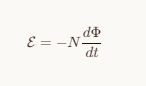
Among them, E is the induced electromotive force, N is the number of coil turns,
dΦ/dt is the rate of change of magnetic flux with time. The negative sign means that the direction of the induced electromotive force always tries to cancel the change in magnetic flux (Lenz's law).
The transformer uses this principle to generate changing magnetic flux in the primary coil through alternating current, which in turn induces voltage in the secondary coil to achieve "wireless" transmission of electrical energy from the primary to the secondary.
1.2 Application of electromagnetic induction principle in transformers
As an electrical device based on the principle of electromagnetic induction, the core function of a transformer is to achieve voltage rise and fall conversion through electromagnetic induction. Specifically, a transformer consists of a primary coil, a secondary coil and an iron core. The role of the iron core is to couple the magnetic fields in the primary and secondary coils, thereby improving energy transfer efficiency. When AC power is applied to the primary coil, the changing current will generate alternating magnetic flux in the iron core. This alternating magnetic flux will pass through the primary coil and the secondary coil at the same time, thus inducing an electromotive force in the secondary coil. According to Faraday's law of electromagnetic induction, the magnitude of the induced electromotive force in the secondary coil is proportional to the rate of change of magnetic flux in the primary coil, and is closely related to the turns ratio of the primary and secondary coils.
When AC voltage V1 is applied to the primary coil (turns N1), an alternating current I1 is generated in the coil, and this current establishes an alternating magnetic flux Φ in the iron core. Due to the high magnetic permeability of the core, most of the magnetic flux is confined within the core and passes through the secondary coil (number of turns N2).
According to Faraday's law, this changing magnetic flux produces induced electromotive forces in the primary and secondary coils respectively:
Primary self-induced electromotive force: 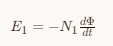
Secondary mutual inductance electromotive force: 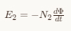
Under the assumption of an ideal transformer (no losses), the input and output voltages are proportional to the number of turns:
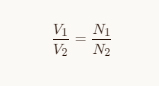
And the current is inversely proportional to the number of turns:
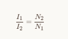
This means that the transformer achieves an inverse transformation of voltage and current while maintaining a basic conservation of power (with a small amount of loss in practice).
II. Structural analysis of transformer
2.1 Iron core
The core of the transformer is its core component, and silicon steel sheets with high magnetic permeability are usually used as the main material. This material has the characteristics of low hysteresis loss and high saturation magnetic induction intensity, which can effectively reduce energy loss and improve the efficiency of the transformer. The structural forms of the core are mainly divided into shell type and core type. The shell type core surrounds the windings inside and is suitable for small transformers; while the core type core is connected by two or more columns to form a closed magnetic circuit and is widely used in medium and large transformers. The main function of the iron core is to provide a magnetic path with low magnetic resistance, thereby enhancing the magnetic flux density and achieving efficient electromagnetic induction. In addition, the design of the core has an important impact on the performance of the transformer. For example, too high a magnetic flux density may lead to magnetic saturation, thereby increasing iron loss and temperature rise. Therefore, it is necessary to rationally select the core material and design its geometry to optimize performance.
2.2 Winding
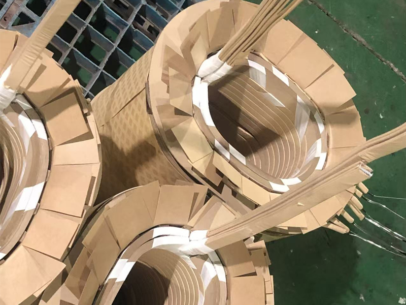
The winding is a key component of the transformer to convert electrical energy. It is usually made of copper or aluminum wire with good electrical conductivity. The primary winding and secondary winding are connected to the input power supply and load circuit respectively, and the conversion of voltage and current is completed under the action of electromagnetic induction. The winding connection methods include series connection and parallel connection. Different connection methods have a significant impact on the relationship between voltage and current. For example, when the primary winding is connected in series, its total number of turns increases, resulting in a higher induced electromotive force; while when the secondary winding is connected in parallel, it provides greater output current capability. In addition, the turns ratio of the primary and secondary windings determines the transformation ratio of the transformer, that is, the proportional relationship between the input voltage and the output voltage. This relationship not only affects the power transmission efficiency of the transformer, but also directly determines its applicable scenarios in the power system. Therefore, rational design of winding composition and connection methods is an important step in improving transformer performance.
2.3 Other structural components
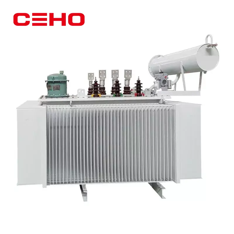
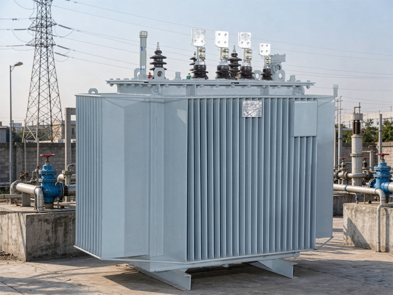
In addition to the iron core and windings, the transformer also includes many auxiliary components such as oil tanks, oil pillows, radiators, etc. These components together constitute the complete structural system of the transformer. As the outer shell of the transformer, the oil tank not only serves as a mechanical support, but also achieves cooling and insulation functions through the insulating oil filled inside. The oil pillow is used to adjust the changes in oil level in the oil tank to prevent changes in oil volume caused by temperature fluctuations from adversely affecting the operation of the transformer. The radiator accelerates heat transfer by increasing the heat dissipation area, thereby effectively reducing the temperature rise generated during the operation of the transformer. The functional coordination of these components has an important impact on the overall performance of the transformer. For example, improperly designed heat sinks can lead to localized overheating, which accelerates the aging of insulation materials and shortens the service life of the transformer. Therefore, in transformer design, the functional matching of each component and its contribution to the overall performance must be fully considered to ensure that the transformer can operate safely and stably under various working conditions.
III. From theory to practice: energy loss and efficiency of transformers
There are various losses in actual transformers during energy transfer:
1. Copper loss
The thermal energy loss caused by the current flowing through the coil resistance is proportional to the square of the current (Pcu=I2 R). Modern transformers use high-conductivity copper wire to minimize this loss.
2. Iron loss
Hysteresis loss: the energy consumed by the continuous rearrangement of magnetic domains during the alternating magnetization process of the iron core material
Eddy current loss: The alternating magnetic flux induces eddy currents inside the iron core, generating Joule heat.
The iron core of modern transformers adopts a laminated structure of silicon steel sheets. Silicon increases the resistivity, and the laminated structure blocks the eddy current path, significantly reducing iron loss.
3. Stray losses
Including eddy current losses caused by leakage flux in structural parts, etc., can be reduced through optimized design and shielding measures.
The efficiency of high-efficiency transformers can reach over 99%, which is the culmination of materials science, electromagnetic design and manufacturing processes.
IV. Methods to improve efficiency
In order to improve the efficiency of transformers, researchers have proposed a variety of strategies from the aspects of optimized design and reasonable operation. In terms of optimized design, selecting high-quality materials and improving structures are key measures to reduce losses. For example, using silicon steel sheets with high magnetic permeability and low loss as the core material can significantly reduce hysteresis loss and eddy current loss; at the same time, by optimizing the lamination method and thickness of the core, the impact of eddy current loss can be further reduced. In terms of winding design, choosing conductive materials with low resistivity (such as copper or aluminum) and optimizing the winding arrangement can effectively reduce copper losses. In addition, reasonable design of the number of winding turns and cross-sectional area can not only balance copper loss and iron loss, but also improve the overload capacity of the transformer.
In terms of reasonable operation, controlling the load rate and selecting appropriate capacity are important means to improve transformer efficiency. Research shows that the efficiency reaches its highest value when the transformer operates between 60% and 80% of the rated load rate. Therefore, in actual operation, the transformer capacity should be reasonably allocated according to the load demand to avoid a single transformer being in a light or heavy load state for a long time. In addition, by using multiple transformers operating in parallel, the number of operating transformers can be flexibly adjusted according to load changes, thereby further improving system efficiency. For large power plants or substations, intelligent monitoring systems can also be used to monitor the operating status of transformers in real time and dynamically adjust load distribution according to actual needs to achieve optimal energy efficiency goals.
In addition to the above methods, regular maintenance and inspection are also important links in improving transformer efficiency. For example, by cleaning the dirt on the winding surface, checking the insulation performance and tightening the connecting parts, additional losses caused by poor contact or insulation aging can be effectively reduced. At the same time, combined with big data analysis and predictive maintenance technology, potential problems can be discovered in advance and targeted measures can be taken, thereby maximizing the service life of the equipment and improving operating efficiency. In summary, through the comprehensive application of multiple means such as optimized design, reasonable operation, and scientific maintenance, the efficiency of the transformer can be significantly improved and provide a strong guarantee for the safe and economical operation of the power system.
V. The Role of Transformers in Modern Energy Systems
Power Grid Transmission: Boosting voltage reduces line current and lowers transmission losses; then stepping down voltage to distribute power to users.
New Energy Integration: Renewable energy sources like wind and solar are connected to the grid through transformers.
Power Electronics Equipment: Micro high-frequency transformers in devices like switching power supplies and chargers.
Electrical Isolation: Provides safe isolation to prevent electric shock hazards.
VI. Conclusion
The working principle of a transformer is a classic application of electromagnetic induction, but its technological development has never stopped. From the first practical transformer at the end of the 19th century to today's high-efficiency smart transformers, this seemingly simple device has always been the core carrier of power technology progress. With the application of new materials, new processes and intelligent technologies, transformers will continue to develop towards higher efficiency, smaller size and more intelligence, playing an irreplaceable role in the process of energy transformation and electrification.
Understanding the entire process of transformers from basic principles to high-efficiency conversion will not only help electrical engineers optimize their designs, but also allow ordinary users to realize that behind the convenient use of electricity in our daily lives is the art of precision electromagnetic energy conversion that condenses a century of wisdom.
Related News
- Start by Choosing the Right JXF
- SG(B)10-10KV environmentally friendly dry-type transformer: How to deliver safe and green answers under non-encapsulated structure?
- What are the hazards of transformer overload operation? How to carry out real-time load monitoring?
- How can oil immersed transformers achieve future green development in the context of "dual carbon"?
- What does the internal structure of a dry-type transformer look like when disassembled?
- How to choose between power cabinet and lighting distribution box?
Leave me a message