English
- English
- Español
- Português
- русский
- Français
- 日本語
- Deutsch
- tiếng Việt
- Italiano
- Nederlands
- ภาษาไทย
- Polski
- 한국어
- Svenska
- magyar
- Malay
- বাংলা ভাষার
- Dansk
- Suomi
- हिन्दी
- Pilipino
- Türkçe
- Gaeilge
- العربية
- Indonesia
- Norsk
- تمل
- český
- ελληνικά
- український
- Javanese
- فارسی
- தமிழ்
- తెలుగు
- नेपाली
- Burmese
- български
- ລາວ
- Latine
- Қазақша
- Euskal
- Azərbaycan
- Slovenský jazyk
- Македонски
- Lietuvos
- Eesti Keel
- Română
- Slovenski
- मराठी
- Srpski језик

Decoding the Protection Logic of Low-Voltage Incoming Cabinets: How to Achieve Safe and Reliable Power Supply?
Decoding the Protection Logic of Low-Voltage Incoming Cabinets: How to Achieve Safe and Reliable Power Supply?
I. Electrical Safety and System Level Positioning
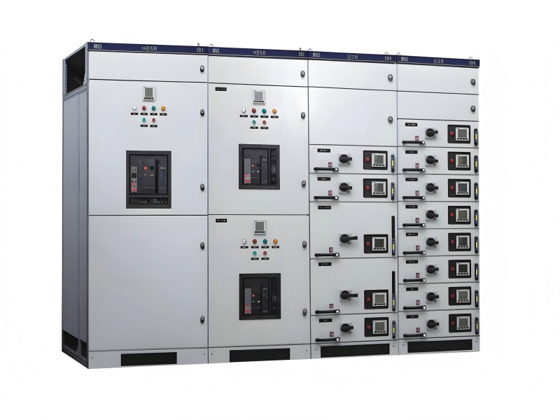
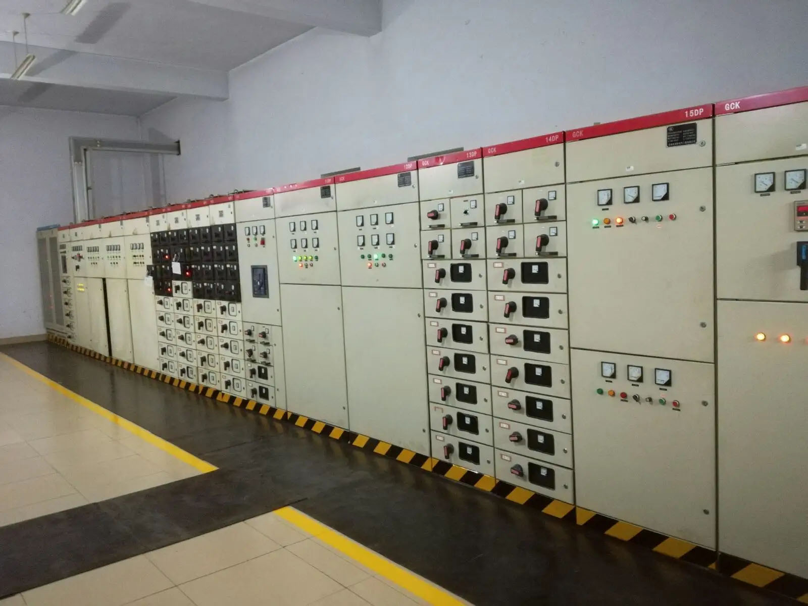
As the total power inlet of the entire low-voltage power distribution system, it is the primary protection gateway for the entire station's power distribution. Failures will affect the entire low-voltage system, so reliability is the top priority.
It is necessary to strictly distinguish the logic of incoming line, bus tie, and outgoing line to prevent incorrect paralleling and incorrect power transmission.
Meet the system insulation coordination requirements; the rated insulation voltage, power frequency withstand voltage, and phase-to-phase/phase-to-ground safety distances must comply with regulations to prevent creepage, breakdown, and phase-to-phase short circuits.
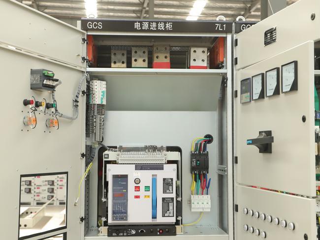
II. Core Electrical Performance (Hard Technology)
The rated working voltage is compatible with the system phase voltage and line voltage, ensuring long-term operation without exceeding the rated withstand voltage, and adapting to on-site power frequency and harmonic conditions.
Rated continuous current-carrying capacity: The long-term temperature rise of the cabinet, main busbar, incoming cable junction, and circuit breaker body shall be controlled, and no overheating, discoloration, or ablation shall occur at the contacts and copper bars.
Short-circuit withstand and breaking capacity
The ultimate/operational short-circuit breaking capacity must be greater than the maximum short-circuit current of the on-site system.
The short-time withstand current and peak withstand current meet the standards; the cabinet body shall not be deformed, the busbar shall not be displaced, and the insulating parts shall not burst under short-circuit impact.
Temperature rise and heat dissipation design: The ventilation ducts of the cabinet are reasonable, with smooth air inlet and outlet at the top and bottom; there is no heat accumulation in the dense busbar and circuit breaker areas, and the temperature rise meets the standards during long-term operation under high load.
III. Protection Logic and Control Functions
Essential protections: Overload long-time delay, short-circuit short-time delay, short-circuit instantaneous, and earth fault protection. The protection curve matches the characteristics of the downstream load.
Equipped with undervoltage/voltage loss tripping function, which automatically trips when the power grid loses power and prevents self-reclosing impact when power supply is restored.
Hierarchical coordination of protection settings: The incoming line protection shall be selectively coordinated with the downstream outgoing line protection to avoid total tripping of the main incoming line due to minor faults in the downstream.
Reliable secondary circuit: The control power supply, closing and opening circuits, and interlocking circuits are wired standardly, without virtual connection or misoperation.
Logic Block Diagram of Low-Voltage Incoming Cabinet Protection (Text Version)
a. Overall Signal Flow Block Diagram
Primary main circuit current → Current Transformer (CT) sampling → Intelligent Controller (ACB Release) → Logic judgment: Long-time delay / Short-time delay / Instantaneous / Earth fault / Undervoltage → Meet the action setting → Issue trip command → Circuit breaker tripping mechanism → Break the incoming main circuit
b. Block Diagrams of Four Major Protection Branches
Overload Long-Time Delay Protection Logic Load current exceeds the standard → CT samples and sends to the controller → Matches the inverse time long-time delay curve → Long delay for slight overload, short delay for severe overload → Delay expires → Trip
Short-Circuit Short-Time Delay Protection Logic Short circuit occurs in the downstream circuit → Short-circuit current triggers the incoming line controller → Incoming line sets a short-time delay of 0.1~0.3s → First wait for the outgoing line circuit breaker to trip instantaneously to eliminate the fault → If the outgoing line fails to trip / the fault is not eliminated → Delay expires → Incoming line trips (prevent overstepping)
Short-Circuit Instantaneous Protection Logic Serious short circuit near the busbar or inside the incoming line cabinet → Short-circuit current far exceeds the instantaneous setting → Trigger directly without short-time delay or waiting → Controller issues command immediately → Circuit breaker trips instantaneously
Earth Fault Protection Logic Method 1: Zero-sequence CT collects the vector sum of three phases + N Method 2: The controller calculates the zero-sequence current through three-phase current operation → Detects that the unbalanced zero-sequence current exceeds the standard → Determines single-phase grounding / insulation damage and leakage → Alarm or delay/instantaneous trip
c. Undervoltage/Voltage Loss Protection Logic Block Diagram
Incoming line voltage drops / external power grid loses power → Undervoltage release monitors the voltage in real time → Voltage is lower than the set threshold → Undervoltage release acts → Forced trip → Automatic reclosing is not allowed after the power grid is restored; closing can only be performed with manual/logical permission
d. Interlocking Logic Block Diagram for Dual Incoming Lines + Bus Tie (Three-Switch Interlock)
1# Incoming Line Closed
↓
Electrical auxiliary contacts + Mechanical connecting rod
↓
Block the closing circuits of 2# incoming line and bus tie
2# Incoming Line Closed
↓
Simultaneously block the closing circuits of 1# incoming line and bus tie
Bus Tie Closed
↓
Simultaneously block the closing circuits of 1# and 2# incoming lines
Core Rule: Only two of the three switches are allowed to be in the closed position at any time; it is strictly prohibited to close all three switches at the same time.
e. Coordination Logic Block Diagram of Upper and Lower Level Protection
Outgoing line cabinet: Short-circuit instantaneous trip → Time difference step coordination → Incoming line cabinet: Short-circuit short-time delay trip → Realization: Downstream faults are tripped by downstream switches, not the main incoming line, ensuring power supply selectivity.
IV. Mechanical Interlock and Electrical Interlock (Top Priority)
Single incoming line: Mechanical interlock between the cabinet door and the switch; the door cannot be opened when closed, and the switch is forced to trip when the door is opened to prevent accidental entry into the live interval.
Dual incoming lines + bus tie scenario: Double interlocking of electrical interlock and mechanical interlock, strictly prohibiting the simultaneous closing of two incoming lines and the illegal paralleling of incoming lines and bus tie, to prevent circulation, short circuit, and transformer burnout.
The mechanical structure of the circuit breaker itself is reliable, with in-place closing and opening, no jamming, and reliable operation of the energy storage mechanism.
V. Cabinet Structure and Busbar Technology
The cabinet plate strength and frame rigidity are sufficient to resist short-circuit electromotive force impact without shaking or deformation.
The main busbar specifications, arrangement, and insulating supports comply with regulations; the phase sequence arrangement is standard, and the phase-to-phase and phase-to-ground insulating partitions are complete.
Complete grounding system: The cabinet frame, door, side panels, and bus tie cabinet are all reliably and centrally grounded, with a continuous and unbroken grounding path.
The protection level is adapted to the on-site environment, preventing dust, splashing, and small animals from entering the cabinet to cause short circuits.
VI. Monitoring and Display Configuration
Standard real-time monitoring of current and voltage, which can check the three-phase balance and voltage deviation.
Equipped with a live display device to intuitively judge whether the incoming line is live, preventing accidental touch and incorrect maintenance.
Necessary configuration of temperature and humidity monitoring and in-cabinet condensation prevention and control to prevent insulation degradation caused by damp condensation.
VII. Environment and Operation Adaptation
Adapt to the on-site altitude, temperature and humidity, dust, and corrosive gas environment; the insulating parts and cabinet body meet the anti-corrosion and weather resistance standards.
In-cabinet condensation and mold prevention design; heating and dehumidification devices are configured in humid areas.
Reserve maintenance space and cable inlet and outlet space; the wiring is neat, and the primary and secondary circuits are routed separately to prevent interference.
VIII. Operation and Maintenance and Safety Inspection
Equipped with obvious breaking points to reliably isolate the power supply during maintenance.
Able to implement the power outage labeling and locking maintenance operation process, with safe operation conditions.
The components are reasonably arranged, facilitating daily inspection, temperature measurement, tightening, and component replacement in the later period, without maintenance dead ends.
Summary
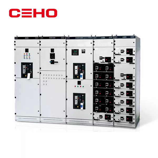
The low-voltage incoming cabinet is the core gateway of the low-voltage power distribution system, undertaking the important tasks of power supply access, safety protection, and load distribution. Its core concerns focus on eight aspects: electrical safety positioning, core electrical performance, protection logic and control, interlocking protection, cabinet and busbar technology, monitoring configuration, environmental adaptation, and operation and maintenance safety. Among them, the protection logic (including overload, short-circuit, earth fault, undervoltage protection) and dual interlocking (mechanical + electrical) are the key to ensuring the safe and stable operation of the cabinet, which can effectively prevent fault expansion, incorrect operation, and safety accidents. The rational matching of all indicators and strict compliance with technical standards are the prerequisites for the long-term reliable operation of the low-voltage incoming cabinet.
FAQ (Frequently Asked Questions)
Q1: What is the core role of the low-voltage incoming cabinet in the power distribution system?
A1: It is the total power inlet and primary protection gateway of the low-voltage system, responsible for power access, fault protection and downstream power distribution, and its reliability directly affects the system's safe operation.
Q2: Why is the selective coordination of protection settings important for incoming line cabinets?
A2: It ensures downstream faults are tripped by outgoing line switches first, avoiding total system outage and ensuring power supply continuity.
Q3: What is the purpose of the double interlock (mechanical + electrical) in the dual incoming line + bus tie scenario?
A3: It prohibits incorrect paralleling of switches, preventing circulation current, short circuit and transformer burnout to ensure system safety.
Q4: What factors should be considered in the environmental adaptation of the low-voltage incoming cabinet?
A4: Adapt to on-site altitude, temperature, humidity, dust and corrosive gas; configure anti-condensation devices and appropriate protection level.
Q5: How to ensure the safety of maintenance operations for low-voltage incoming cabinets?
A5: Equip obvious breaking points, implement power outage labeling and locking, and arrange components reasonably to avoid maintenance dead ends.
Related News
- Start by Choosing the Right JXF
- SG(B)10-10KV environmentally friendly dry-type transformer: How to deliver safe and green answers under non-encapsulated structure?
- What are the hazards of transformer overload operation? How to carry out real-time load monitoring?
- How can oil immersed transformers achieve future green development in the context of "dual carbon"?
- What does the internal structure of a dry-type transformer look like when disassembled?
- How to choose between power cabinet and lighting distribution box?
Leave me a message