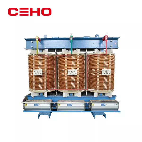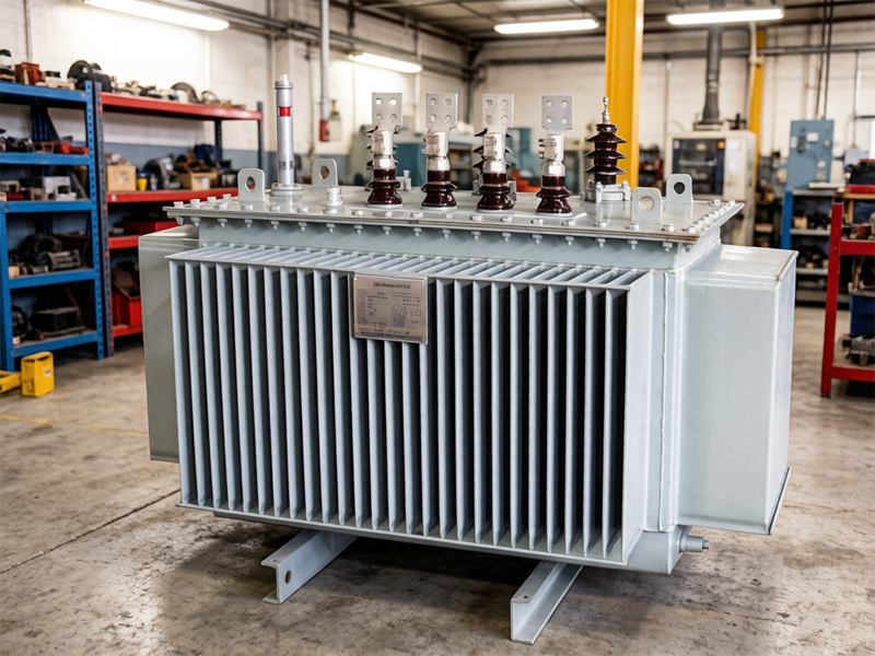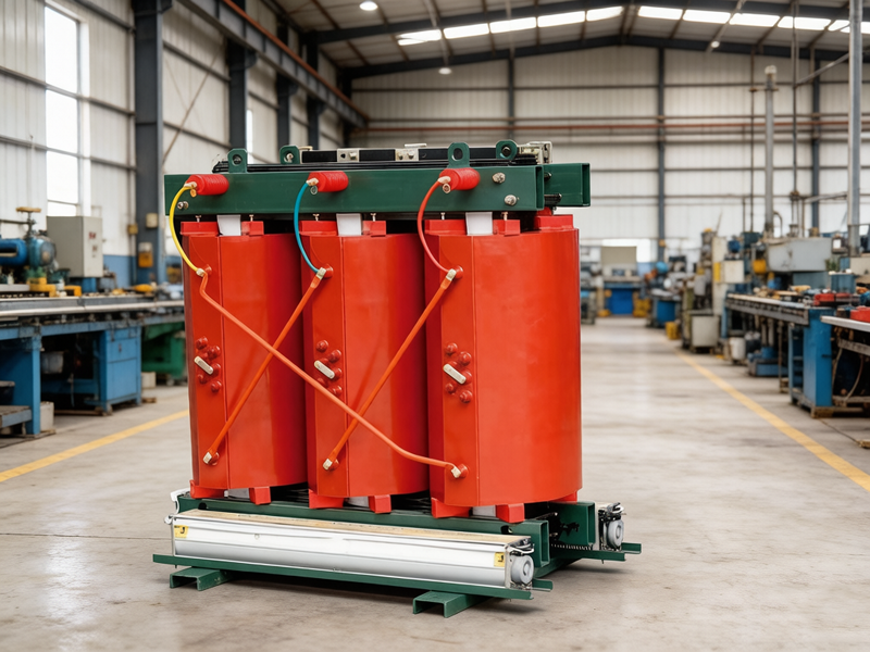
What Is a Power Transformer
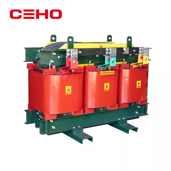
A power transformer is a stationary electrical device that utilizes the principle of electromagnetic induction to convert alternating current (AC) of one voltage and current level into AC of the same frequency but with a different voltage and current level (or levels). In other words, it is a device designed to transform an AC voltage (or current) of a certain value into another voltage (or current) of a different value (or values) at the same frequency. Power transformers are among the primary pieces of equipment in power plants and substations.
What is the core operating principle?
Based on Faraday’s law of electromagnetic induction, the core formula is: voltage ratio ≈ turns ratio (U1/U2 ≈ N1/N2):
Magnetic coupling: When alternating current flows through the primary winding, it generates an alternating magnetic flux in the core.
Induced Electromotive Force: The magnetic flux passes through the secondary winding, inducing an electromotive force.
Energy Transfer: Electrical energy is transferred “wirelessly” from the primary side to the secondary side via the magnetic field, achieving electrical isolation and voltage transformation.
What Is the Function of a Power Transformer?
Power transformers transform voltage, isolate power sources, and transmit electrical energy; they are key equipment in power systems for achieving voltage level conversion and ensuring safe power supply.
1. Core Function: Voltage Transformation (Step-up + Step-down)
Step-up: Power plants generate relatively low voltage. Using a transformer to step up the voltage enables long-distance power transmission, significantly reducing line losses and improving transmission efficiency.
Step-down: As power is delivered to the user end, it is stepped down in stages to become safe and usable low-voltage power (e.g., 0.4 kV/220 V).
2. Electrical Isolation
There is only magnetic coupling between the high- and low-voltage windings, with no direct electrical connection. This achieves:
Safety isolation between personnel and equipment, suppression of interference, and reduction of the impact of ground faults.
3. Current Transformation
As voltage increases, current decreases; as voltage decreases, current increases, meeting the current requirements of different loads.
4.Impedance Transformation
Altering the system’s equivalent impedance to coordinate with relay protection and improve system stability.
What are power transformers used for?
They are widely used in lighting, machine tool electrical equipment, mechanical and electronic equipment, medical equipment, rectifier units, the military, aerospace, and other fields. The product performance meets various special requirements of users.
What are the main components of a power transformer?
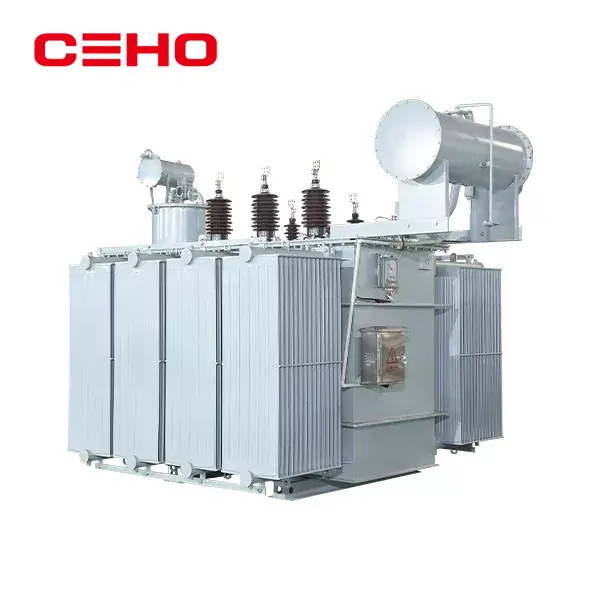
A. Desiccant (silica gel cartridge): Filled with silica gel, it connects the insulating oil in the oil reservoir (oil tank) to the atmosphere. The desiccant absorbs moisture and impurities from the air to maintain the good insulation performance of the internal windings; discoloration or deterioration of the silica gel can easily cause blockage.
B. Oil Level Gauge: Indicates the transformer’s oil level. Typically, the level is around +20°C. If the level is too high, oil must be drained; if too low, oil must be added. In winter, when temperatures are low and the load is light, the oil level changes little or drops slightly. In summer, when the load is heavy, the oil temperature rises and the oil level also rises slightly; both scenarios are normal.
C. Oil Reservoir: Regulates the oil volume in the tank to prevent excessive oxidation of the transformer oil; it features a filling port at the top.
D. Explosion Relief Valve: Prevents the risk of explosion caused by a sudden increase in pressure within the tank due to accidents.
E. Signal Thermometer: Monitors the operating temperature of the transformer and issues an alert. It indicates the temperature of the upper layer of oil; the temperature of the transformer windings is typically 10°C higher than that of the upper layer of oil. National standards stipulate: The maximum operating temperature of transformer windings is 105°C; (i.e., when the ambient temperature is 40°C), the upper oil temperature must not exceed 95°C. It is generally recommended to set the monitoring temperature (upper oil temperature) at 85°C or below.
F. Tap changer: Changes the voltage ratio by altering the number of turns in the high-voltage winding through the tap changer.
G. Gas Signal Relay: (Gas Relay) Provides protection against light and heavy gas signals. The upper contact triggers a light gas signal, generally used for alarm signaling to indicate abnormal transformer operation; the lower contact triggers a heavy gas signal, which, upon activation, sends an alarm signal while simultaneously tripping the circuit breaker, causing the transformer to trip, and triggering an alarm; Normally, a gas relay is filled with oil, indicating the absence of gas. When gas enters the tank, it flows into the gas relay; once it reaches a certain level, the gas displaces the oil, causing the contacts to open. Open the outer cover of the gas relay; there are two adjustment rods on top. Unscrew one of the caps to release the gas from the relay; the other adjustment rod is the protection operation test knob. When performing live-line operations, insulated gloves must be worn, and safety must be emphasized.
Grounding of Power Transformers
1. The transformer casing must be reliably grounded. The working neutral conductor and the neutral grounding conductor must be laid separately; the working neutral conductor must not be buried underground.
2. The neutral grounding circuit of the transformer should be configured with removable connecting bolts near the transformer.
3. For transformers equipped with valve-type surge arresters, the grounding must satisfy the “three-in-one” requirement; that is, the transformer neutral point, the transformer casing, and the surge arrester grounding must be connected to a single common grounding point.
4. The grounding resistance shall be ≤4 ohms.
Maintenance and Servicing of Power Transformers
I. Routine Maintenance and Inspection
Cleaning and Maintenance
Regularly remove dust and oil residue from the transformer’s surface to keep it dry and clean, thereby preventing any impact on heat dissipation performance. Pay special attention to cleaning the radiators and ventilation openings to prevent blockages.
Bushings and insulators should be kept clean to prevent flashovers caused by accumulated dirt.
Oil Level and Quality Monitoring
Check that the oil level in the oil reservoir is normal and that the oil is clear and free of impurities. If the oil level is too low, top up the oil; if too high, drain excess oil.
Insulating oil should undergo dielectric strength and impurity testing every 3 years (with shorter intervals required during full-load operation). Degraded oil must be filtered or replaced to ensure a breakdown voltage of ≥40 kV.
Temperature Monitoring
The upper oil temperature should not exceed 85°C. Hotspot temperatures in the windings must be controlled below 98°C (dry-type) or 80°C (oil-immersed). Abnormal temperature rises may indicate overloading or cooling system failure.
II. Regular Professional Inspections
Insulation Performance Testing
Test insulation resistance and dielectric loss every 2 years; high-voltage insulation resistance must not be less than 70% of the factory value.
The difference in DC resistance between the three phases of the windings should be ≤2%, and the variation compared to historical data should not exceed 2%.
Cooling System Maintenance
Check the operating status of fans and oil pumps, clean dust from radiators, and ensure unobstructed oil flow. Forced air cooling systems require periodic testing of start-stop functions.
Grounding and Lightning Protection Inspection
Measure grounding resistance annually to ensure it is ≤4Ω; the grounding of surge arresters must be connected to the transformer’s neutral point and casing (three-in-one grounding).
III. Maintenance of Key Components
Tap Changer
Regularly inspect the tightness of contacts and check for scorching; the switching mechanism must operate smoothly without sticking. On-load tap-changing transformers must be operated in accordance with procedures.
Gas Relays
When a light gas alarm is triggered, check the oil level and gas properties; if a heavy gas alarm is triggered, immediately investigate internal faults.
Breather and Silica Gel
Replace the silica gel in the breather when it turns pink to prevent moisture from entering the oil reservoir.
IV. Handling Special Operating Conditions
Overload Operation: When the long-term load factor exceeds 80% or the ambient temperature exceeds 40°C, shorten the inspection cycle to 6 months and increase the frequency of oil gas chromatography analysis.
Aged Transformers: Equipment in operation for over 15 years should undergo a comprehensive inspection every six months, even at low loads.
V. Safety Precautions
During maintenance, power must be disconnected and the equipment grounded; use professional tools and have the work performed by qualified personnel.
In the event of a transformer fire, immediately cut off the power supply and extinguish the fire with a carbon dioxide or dry powder fire extinguisher; the use of water is strictly prohibited.
If you need to purchase a transformer, please contact us. We’d be happy to assist you.