English
- English
- Español
- Português
- русский
- Français
- 日本語
- Deutsch
- tiếng Việt
- Italiano
- Nederlands
- ภาษาไทย
- Polski
- 한국어
- Svenska
- magyar
- Malay
- বাংলা ভাষার
- Dansk
- Suomi
- हिन्दी
- Pilipino
- Türkçe
- Gaeilge
- العربية
- Indonesia
- Norsk
- تمل
- český
- ελληνικά
- український
- Javanese
- فارسی
- தமிழ்
- తెలుగు
- नेपाली
- Burmese
- български
- ລາວ
- Latine
- Қазақша
- Euskal
- Azərbaycan
- Slovenský jazyk
- Македонски
- Lietuvos
- Eesti Keel
- Română
- Slovenski
- मराठी
- Srpski језик

Why Do Transformers Need an Iron Core?
As the core equipment for power transmission and distribution, one of the most important components in the internal structure of transformers is the iron core. Seemingly simple laminated metal blocks, they carry the key mission of efficient operation of transformers.
The iron core of a transformer is also a relatively valuable part of the transformer. Often, the iron core of a transformer is easily lost, and the operation of the entire transformer will be affected if it is lost. Why add an iron core to a transformer?
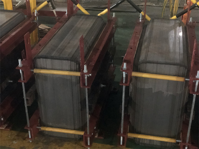
I. The core function of the iron core: to build an efficient magnetic circuit
1. Concentrate and guide magnetic flux
When alternating current passes through the primary coil, an alternating magnetic field is generated. If there is no iron core, the magnetic field will disperse in the air to form "leakage magnetic field", resulting in a significant loss of energy. The iron core (usually made of stacked silicon steel sheets) has high magnetic permeability characteristics, which can effectively confine magnetic field lines (magnetic flux) in a specific path, forming a closed magnetic circuit, allowing the vast majority of magnetic field lines to pass through the secondary coil, thereby achieving efficient energy transfer.
2. Enhance magnetic coupling efficiency
The presence of the iron core significantly enhances the magnetic coupling coefficient between the primary coils. Experiments have shown that high-quality iron cores can increase the coupling coefficient to above 0.95, while hollow transformers without iron cores typically have a coupling coefficient of less than 0.7. This means that over 95% of the magnetic field energy is effectively utilized, significantly improving the energy transfer efficiency of the transformer.
II. Material Science of Iron Core: Why Silicon Steel Sheet?
Transformer cores are mostly made of silicon steel sheets. The actual transformer always operates in AC state, and power loss is not only generated in the resistance of the coil, but also in the iron core under the magnetization of alternating current. The power loss in the iron core is usually referred to as "iron loss", which is caused by two reasons: hysteresis loss and eddy current loss.
Hysteresis loss is the iron loss caused by the presence of hysteresis in the magnetization process of an iron core. The magnitude of this loss is proportional to the area enclosed by the hysteresis loop of the material. The hysteresis loop of silicon steel is narrow, and using it as the iron core of transformers has smaller hysteresis losses, which can greatly reduce its heat generation. A sheet-like iron core can reduce another type of iron loss - "eddy current loss".
When a transformer is working, there is alternating current in the coil, and the magnetic flux it generates is of course alternating. The changing magnetic flux generates induced current in the iron core. The induced current generated in the iron core flows in a plane perpendicular to the direction of magnetic flux, hence it is called eddy current. Eddy current losses also cause the iron core to heat up.
In order to reduce eddy current losses, the iron core of the transformer is stacked with silicon steel sheets that are insulated from each other, allowing eddy currents to pass through a narrow circuit with a smaller cross-section and increase the resistance of the eddy current flow path; Meanwhile, the silicon in silicon steel increases the material's electrical resistivity and also reduces eddy currents.
1. Reduce eddy current losses
Alternating magnetic fields will induce vortex like currents (eddy currents) in magnetic materials, resulting in thermal losses. Silicon steel sheets solve this problem through two ways:
Add 2-5% silicon to increase material resistivity
Thin film stacking design increases eddy current path resistance
This structure reduces eddy current losses to less than 20% of the total core losses.
2. Reduce hysteresis loss
Silicon steel has a narrow hysteresis loop, which means it consumes less energy in the magnetization demagnetization cycle. The hysteresis loss of modern oriented silicon steel is reduced by 60-70% compared to ordinary low carbon steel.
3. Inter chip insulation treatment
Each silicon steel sheet is coated with an inorganic insulation layer on its surface to ensure electrical isolation between the stacked sheets while not obstructing the passage of magnetic flux.
III. Engineering optimization of iron core: shape and process
1. Evolution of structural design
E-type iron core: the most common structure, easy to manufacture
C-type iron core: using winding technology, with seamless magnetic circuit
Amorphous alloy iron core: a new material with iron loss only 20-30% of that of silicon steel
2. Optimization of seam process
The joint of the iron core laminations adopts a stepped overlap design to reduce the air gap magnetic resistance caused by magnetic circuit discontinuity, which can reduce the no-load current by 15-25%.
IV. Limitations of ironless transformers
Although some high-frequency applications may use hollow transformers, power transformers with a frequency of 50/60Hz must use iron cores for the following reasons:
Under the same power, the volume of the hollow transformer will increase by 5-8 times
2. Energy transfer efficiency is usually below 70%
3. A large cross-sectional coil is required, which increases copper material consumption by 3-5 times
4. Generate strong leakage magnetic field, causing interference to surrounding equipment
V. Challenges and solutions brought by iron cores
While the iron core brings advantages, it also introduces some engineering challenges:
1. Core loss (no-load loss)
Mainly generated by hysteresis and eddy current effects, accounting for 30-50% of the total losses in transformers. The solution includes:
• Use oriented silicon steel with high magnetic conductivity and low loss
• Using laser irradiation to refine magnetic domains
• Optimize the cross-sectional shape of the iron core to reduce local magnetic saturation
2. Iron core vibration and noise
The magnetostriction effect causes periodic deformation of the iron core, resulting in 100/120Hz fundamental frequency noise. Modern transformers use:
• Adopting a step-by-step overlap process to reduce magnetic flux discontinuity
• Increase compression force and optimize clamp structure
• Add damping material between the iron core and the oil tank
3. Grounding problem of iron core
To prevent static electricity accumulation, the iron core must be reliably grounded at a single point. Multiple grounding points can generate circulating currents, causing local overheating. Modern transformers are equipped with an online monitoring system for iron core grounding.
VI. Future development direction
1. Application of new materials
• Amorphous alloy: extremely low iron loss, especially suitable for distribution transformers with low load rates
• Nanocrystalline alloy: With excellent comprehensive performance, it has been applied in high-frequency transformers
•Soft magnetic composite materials: providing new possibilities for three-dimensional magnetic circuit design
2. Intelligent iron core
Integrated fiber optic sensors for real-time monitoring of iron core temperature, vibration, and partial discharge, achieving predictive maintenance.
Conclusion
The transformer core is not a simple "iron block", but a core component that embodies electromagnetic, materials science, and precision manufacturing technology. The evolution history of iron cores, from Faraday's use of iron rings in 1831 to today's use of laser processed high permeability silicon steel sheets, is a history of transformer energy efficiency improvement. It has transformed transformers from laboratory principle verification equipment into energy conversion hubs with efficiency exceeding 99% in modern power systems. It is these seemingly ordinary layers of silicon steel sheets that silently support the efficient and stable operation of the global power network, and can be called the "invisible backbone" of the power industry.
FAQ
Q1: What is the main function of the transformer core?
A1: The primary function of the core is to provide a low-reluctance magnetic path. It efficiently confines and channels the alternating magnetic field generated by the primary winding to the secondary winding, thereby greatly enhancing energy transfer efficiency. Without the core, the magnetic field would largely disperse in the air, resulting in very poor coupling.
Q2: How does the core improve the efficiency of a transformer?
A2: The high permeability of the core significantly reduces the magnetizing current required to establish a magnetic field of the same strength, thereby lowering copper losses (resistance losses in the winding). It also concentrates the magnetic flux lines, reduces flux leakage, and ensures tighter magnetic coupling and more accurate voltage transformation.
Q3: Why are transformer cores usually made of laminated silicon steel sheets instead of solid iron?
A3: A solid iron core would experience enormous eddy current losses under an alternating magnetic field, leading to heating and reduced efficiency. Laminated silicon steel sheets are insulated from each other, which breaks the path for large eddy currents and confines them within each lamination. The addition of silicon increases the material's resistivity, further suppressing eddy currents.
Q4: How does the permeability of the core affect transformer performance?
A4: Higher permeability means less magnetizing current is needed to establish the magnetic field, resulting in lower no-load losses and higher efficiency. It also allows for greater inductance or power capacity within the same physical dimensions.
Q5: Can a transformer work without an iron core?
A5: Yes, it can work and is called an "air-core transformer." However, it relies solely on air for coupling, which has very high magnetic reluctance and significant flux leakage, leading to a very low coupling coefficient. Thus, it is only suitable for high-frequency, low-power, or specific applications where efficiency is not critical (e.g., in radio frequency circuits).
Q6: What are the types of core losses, and how can they be reduced?
A6: Core losses primarily include Hysteresis Loss and Eddy Current Loss.
• Hysteresis Loss: Caused by internal friction as the magnetic domains realign with the alternating field. It can be reduced by using soft magnetic materials with a narrow hysteresis loop (e.g., high-grade silicon steel, amorphous alloys).
• Eddy Current Loss: Caused by circulating currents induced within the core by the alternating field. It can be minimized by using laminated thin sheets, adding silicon to increase resistivity, or using powdered iron cores.
Together, these are known as "iron losses" or "no-load losses."
Q7: How does the shape of the core (e.g., E-type, toroidal) affect the transformer?
A7:
• E/UI-Type: Simple to manufacture, easy to wind coils, and low cost. However, the magnetic path has gaps at joints, leading to some flux leakage and loss.
• Ring-Type : Continuous magnetic path with no air gap, resulting in minimal flux leakage, high efficiency, and low electromagnetic interference. However, winding is more complex and costly.
• C-Type: Offers a balance. Made from two half-rings, it provides better magnetic performance than E-cores and is easier to wind than toroidal cores.
Q8: Does the transformer core need to be grounded? Why?
A8: Yes, and it is typically grounded at a single point only. This prevents the core and metal structural parts from accumulating charge due to electrostatic induction, which could cause intermittent discharges that damage insulation and oil (in oil-immersed transformers). Multiple ground points would create circulating currents, leading to local overheating.
Q9: How are eddy currents generated in the core, and how are they suppressed?
A9: According to Faraday's law of electromagnetic induction, an alternating magnetic field passing through the conductive core induces an electromotive force, which drives swirling currents known as eddy currents. Suppression methods include:
1. Using Lamination: The core is made of thin, insulated sheets stacked perpendicular to the magnetic flux to break up long eddy current paths.
2. Increasing Material Resistivity: For example, adding silicon to steel.
3. Using Materials with Better High-Frequency Characteristics: Such as ferrite, amorphous alloys, or noncrystalline materials.
Q10: How are core materials different for high-frequency transformers (e.g., in switching power supplies)?
A10: At high frequencies, eddy current and hysteresis losses increase dramatically. Therefore, materials with extremely high resistivity and low high-frequency loss are essential. Common materials include:
• Ferrite: Very high resistivity and low loss at high frequencies, but relatively low saturation flux density. Widely used from kHz to MHz ranges.
• Amorphous and Noncrystalline Alloys: Feature very high permeability and extremely low losses, used in high-performance mid-to-high frequency applications.
• Powdered Cores (e.g., iron powder, Permalloy): Distributed air gaps prevent saturation, often used in energy storage and filter inductance.
Next:
-
Related News
- What GT-12 Actually Is
- Power Transformers in School: The Invisible Heart of Campus Energy
- How to Choose the Right Transformer
- How Do You Choose the Right High Voltage Power Cable?
- Copper vs Aluminum Windings in Transformers: Which Should You Choose?
- What Makes Amorphous Metal Distribution Transformers Worth It?
Leave me a message
New Products

News Recommendations